

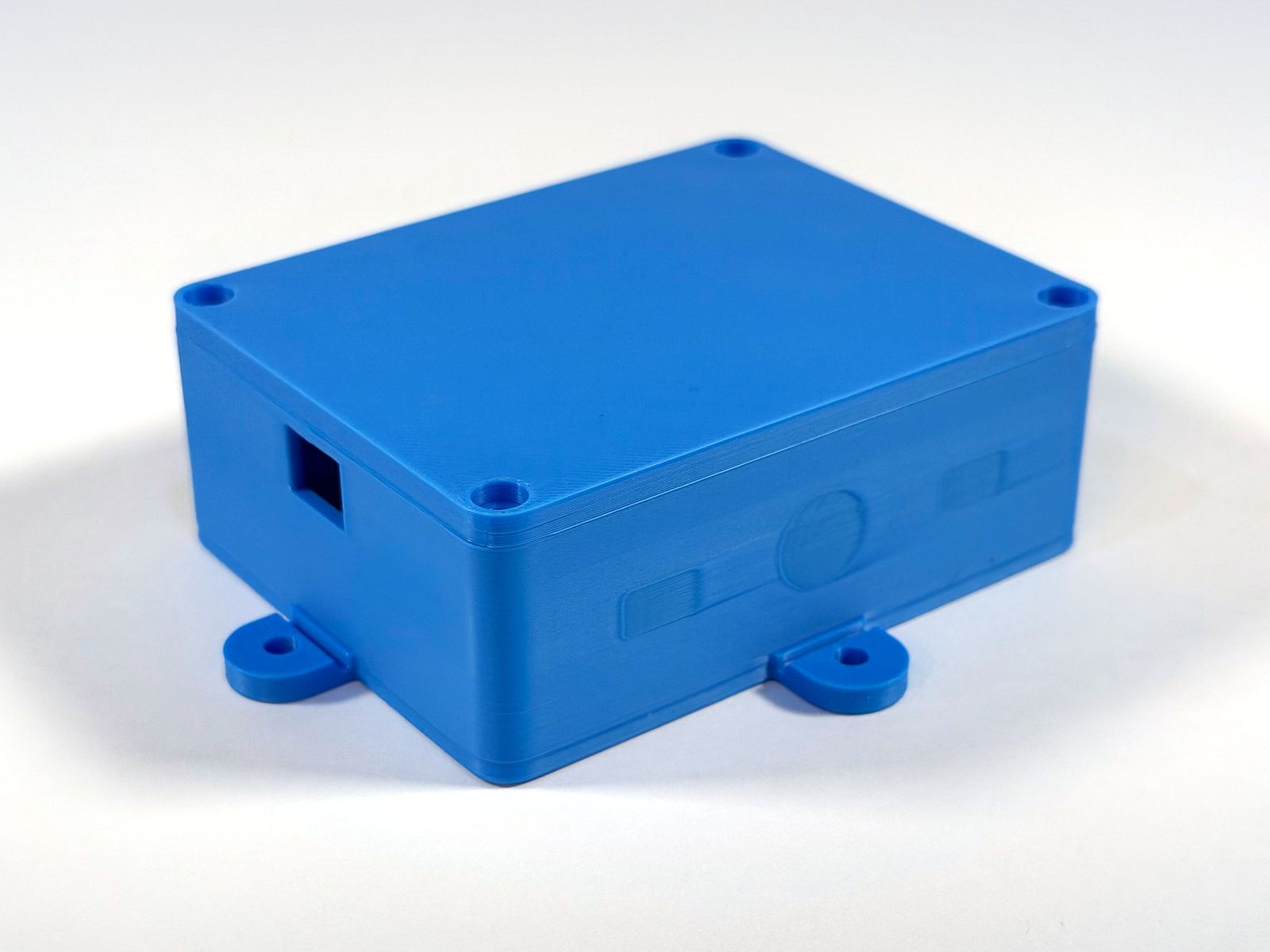
Enclosure 03
Raspberry Pi Pico 2 Breakout Enclosure (v1)
A screw-lid box for the Raspberry Pi Pico 2 on its screw-terminal breakout. You only cut the openings you need.
Printed and test-fit
v1
Description
This enclosure is built around one specific pairing: a Raspberry Pi Pico 2 plugged into a Pi Pico screw-terminal breakout board (78 × 57 mm, 2×20 terminals plus a 3-pin SWD block). The walls print solid, with thin-skin knockouts you cut out from inside only where you need a wire or a cable gland. The rest stays closed.
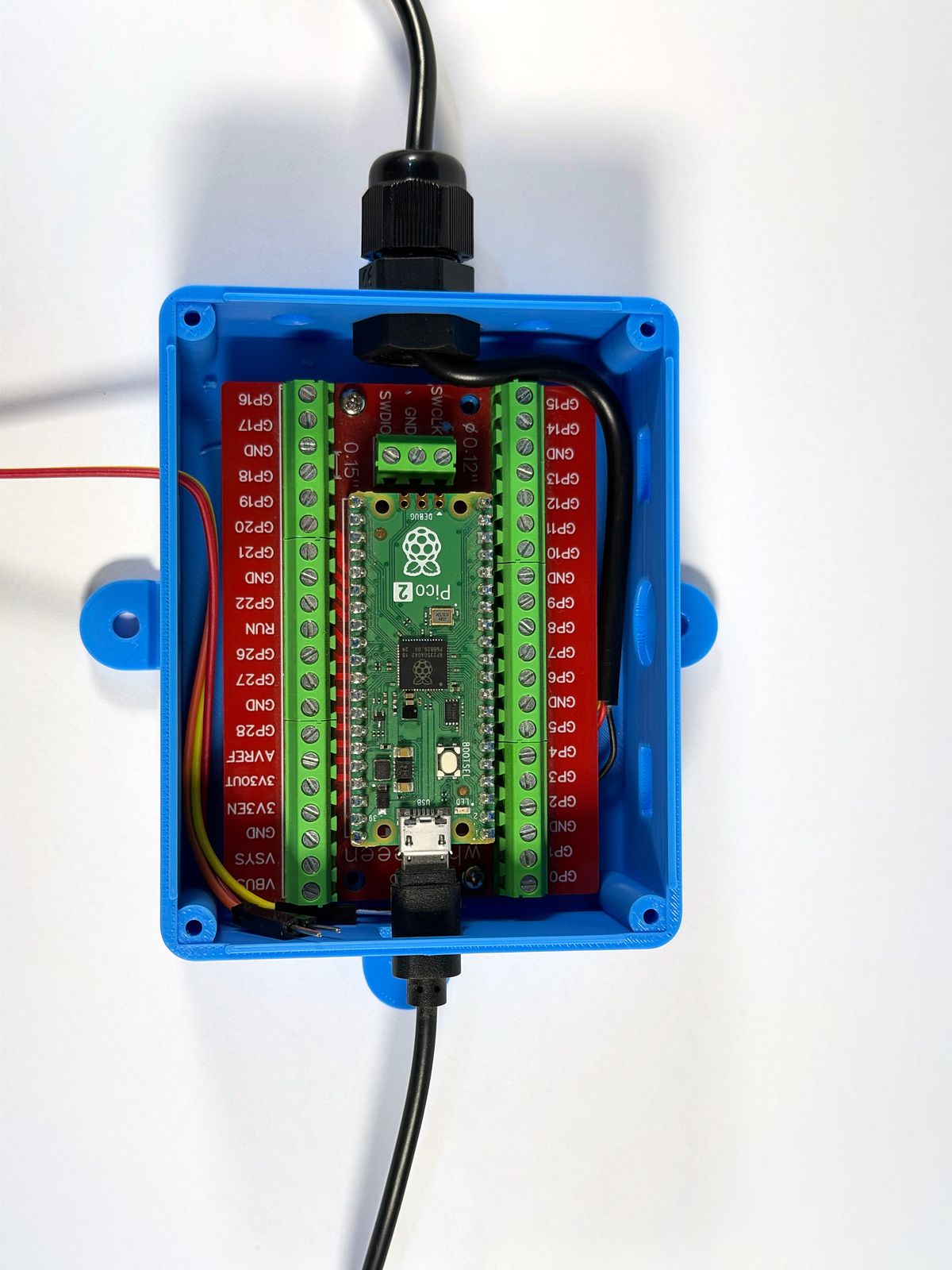
I printed and test-fit it on my Bambu Lab A1 before posting it. The Pico 2 and breakout sit on the built-in standoffs, and every terminal is reachable with the lid off. The micro-USB opening lines up with the Pico's port, so you can program and power it with the lid on, using a slim micro-USB cable. A PG7 gland fits the SWD-end knockout, but it's tight: the locknut clears the breakout by only about 2–3 mm and sits in front of the SWD block's wire entries, so wire that block first or put the gland in a long wall. I haven't tested a gland in a long wall yet; check that your gland's inside thread plus locknut is under about 6 mm.
It prints as two parts (base and lid) with no supports. The OpenSCAD source is included if you want to change things.
Features
- Thin-skin knockouts that look like solid wall until you cut one out:
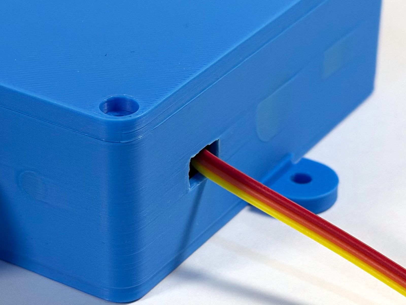
- Each long wall has one PG7 (12.5 mm) round between two 10 × 6 mm slots.
- The SWD end has one PG7 between two 5 mm rounds.
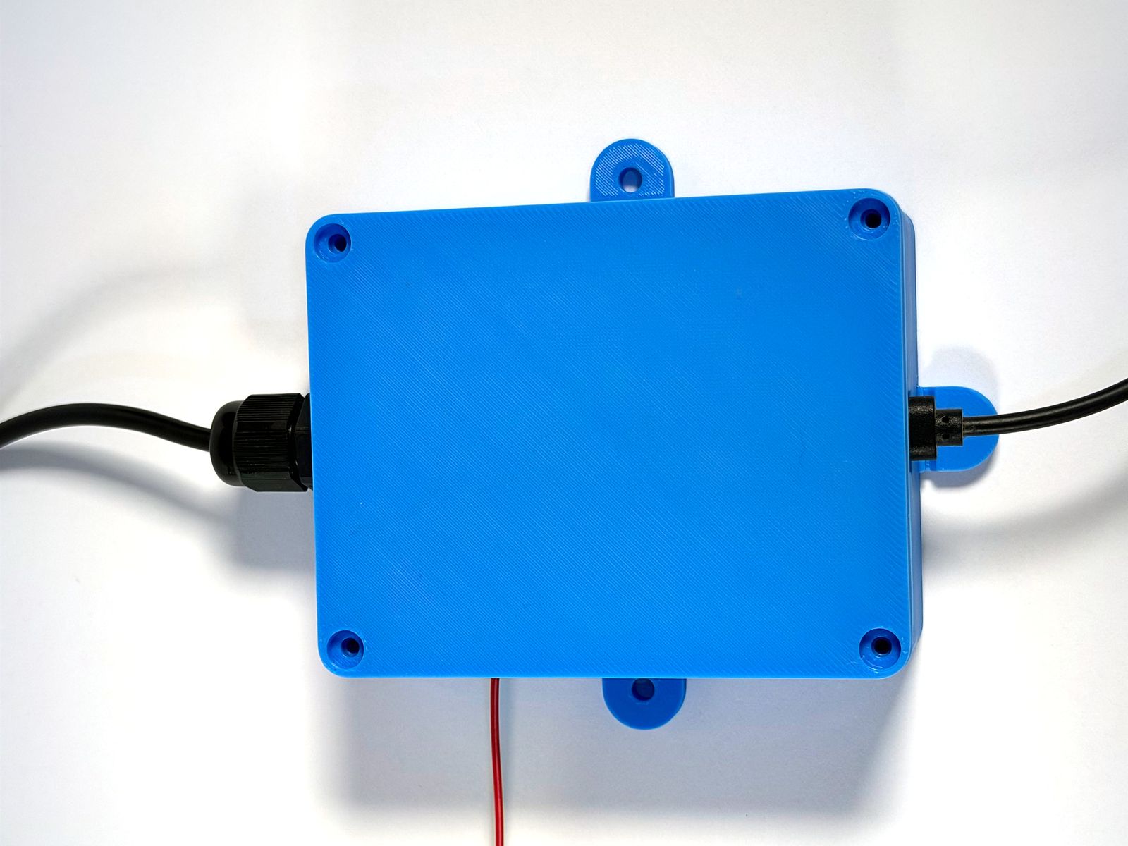
- A 12 × 9 mm micro-USB opening lined up with the Pico's port. Use a slim-body cable; bulky or right-angle plugs may not reach.
- Four break-off mounting tabs for #6–#8 screws (4.3 mm holes), with score grooves so you can snap off the ones you don't need.
- Two sealed floor keyhole slots for #6–#8 pan-head screws.
- A 4 mm screw-down lid with counterbored corner holes and a locating lip.
- Parametric OpenSCAD source with Customizer options for mounting and wire exits (zip-tie tunnels, magnet pockets and a cable clamp are off by default). It needs OpenSCAD 2021.01 or newer.
Tip: an X-Acto #104 concave carving blade opens the knockouts cleanly.
Download
Download the print files on MakerWorld:
Questions? Email support@azdroidworks.com
Photos
Before cutting
-
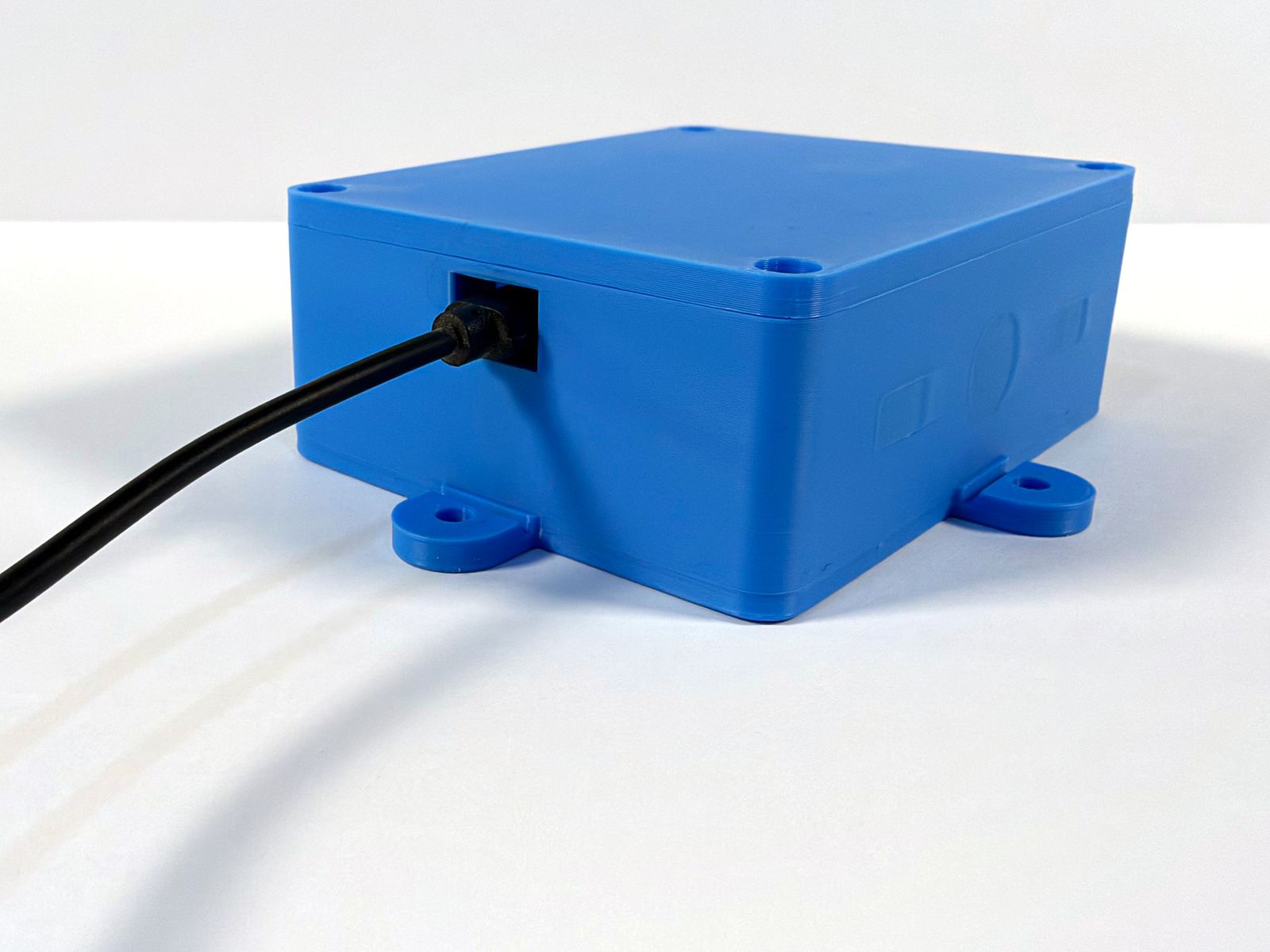
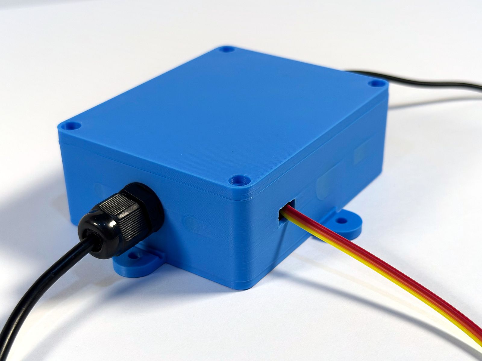
03Program and power the Pico with the lid on -
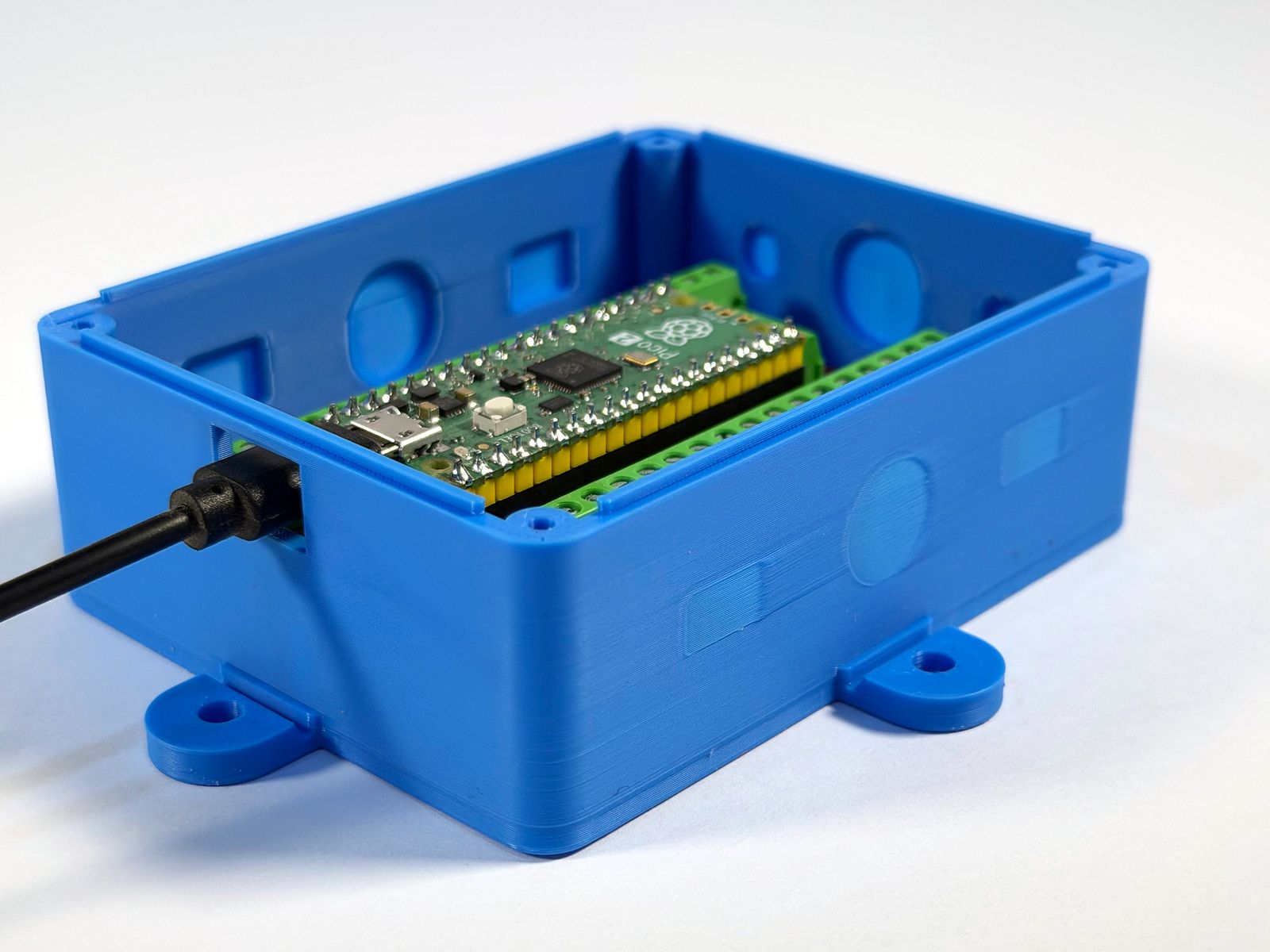
04A slim micro-USB cable reaches the Pico's port -
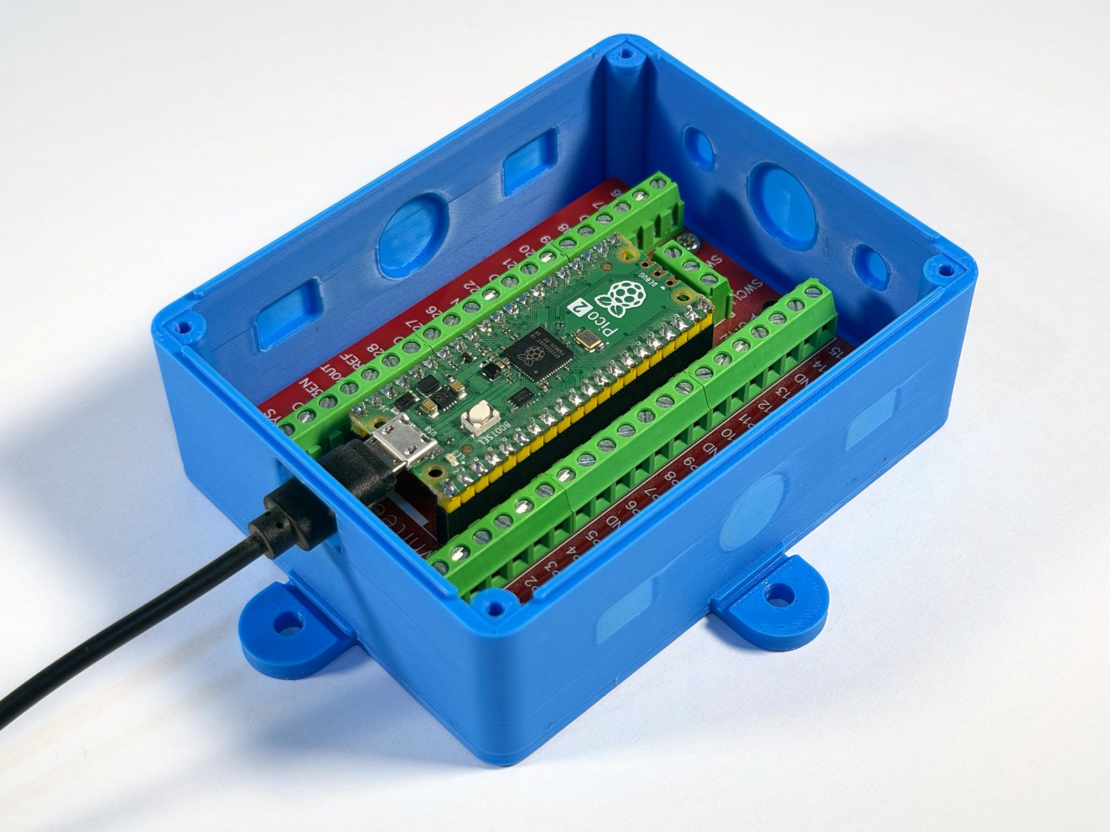
05The Pico 2 and screw-terminal breakout sit on built-in standoffs -
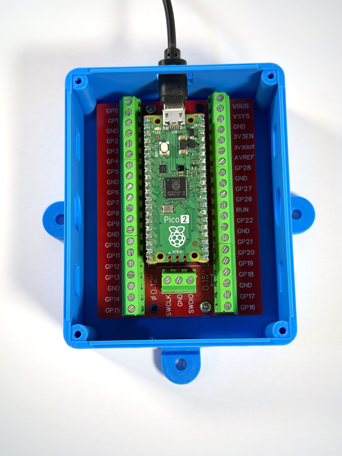
06All 43 terminals stay reachable with the lid off -
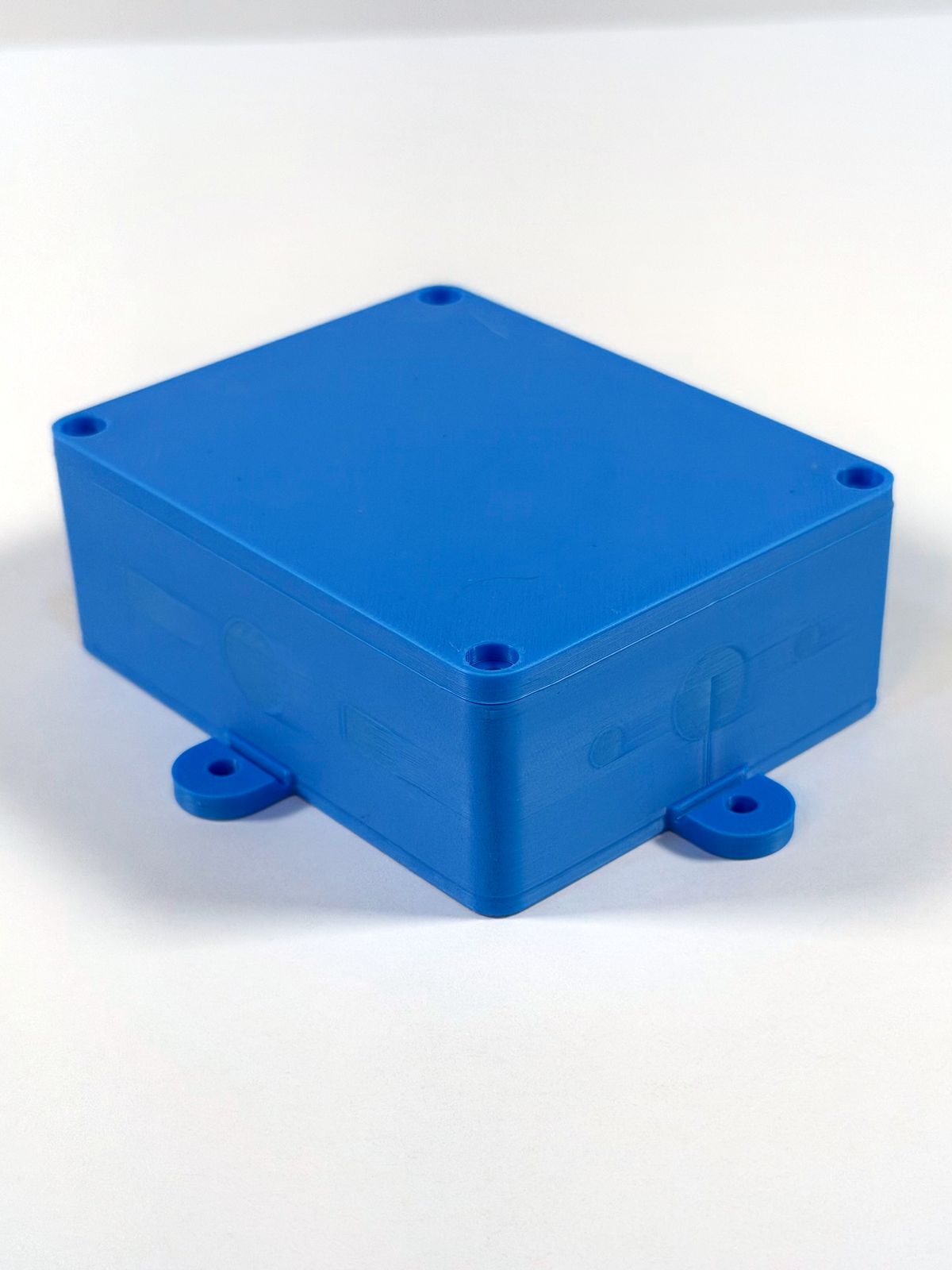
07Knockouts stay closed until you need them -
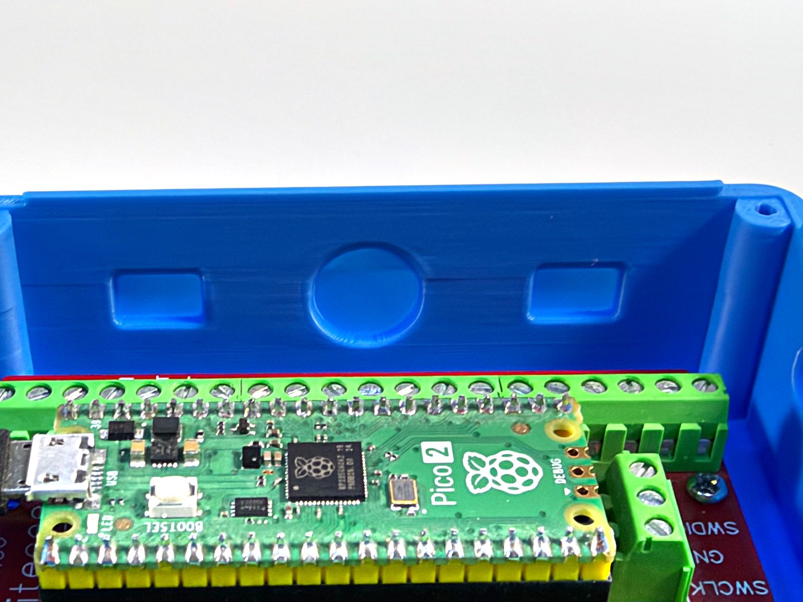
08Long wall from inside: two slots and a PG7 knockout at terminal height -
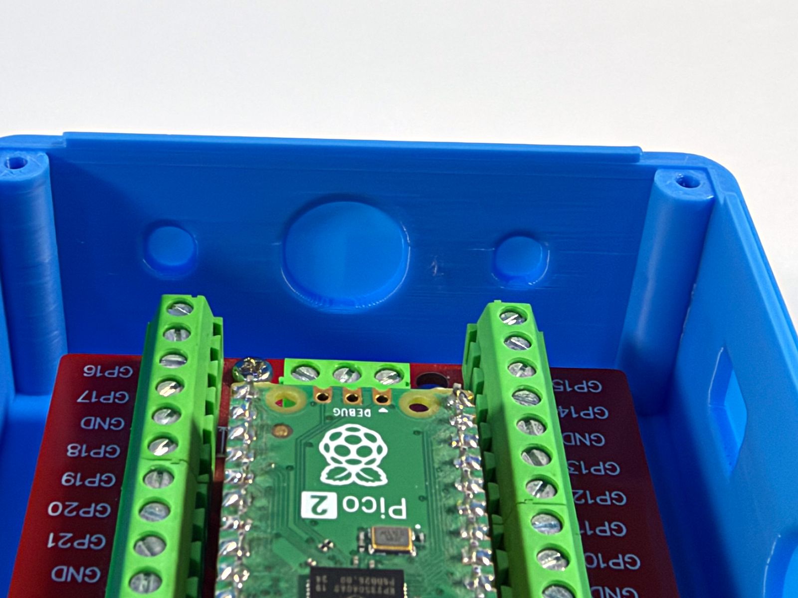
09SWD end from inside: a PG7 between two 5 mm rounds -
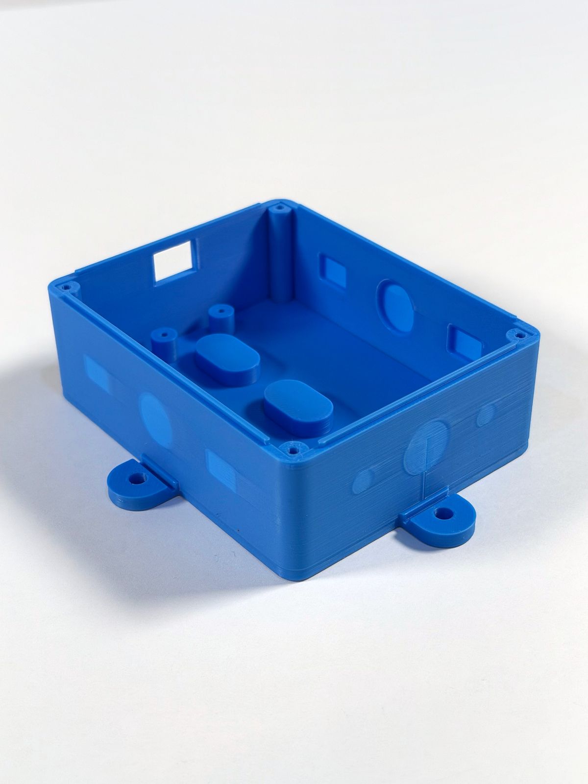
10Empty base with standoffs, posts and sealed keyhole bosses -
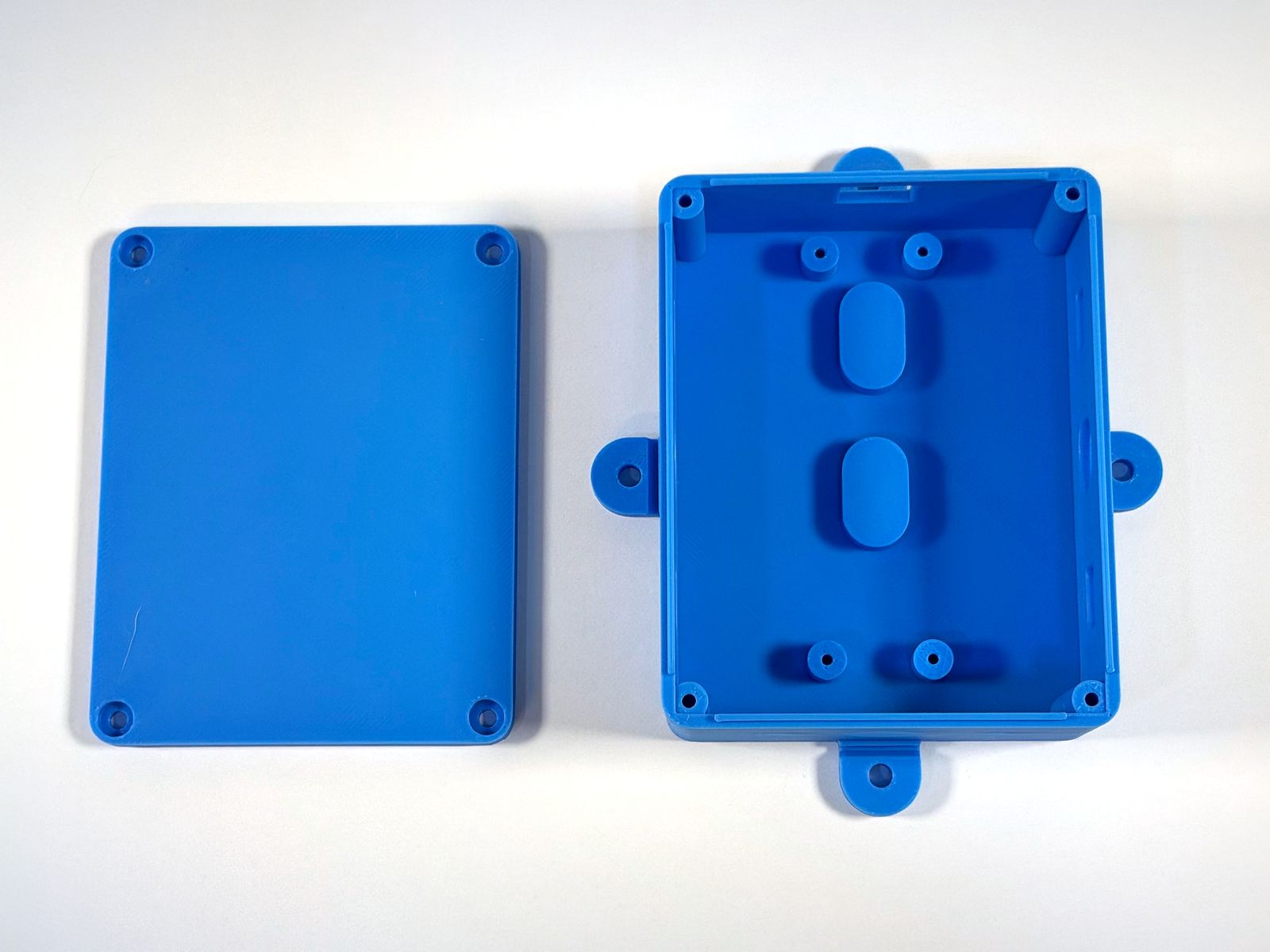
11Two parts, base and lid, printed without supports -
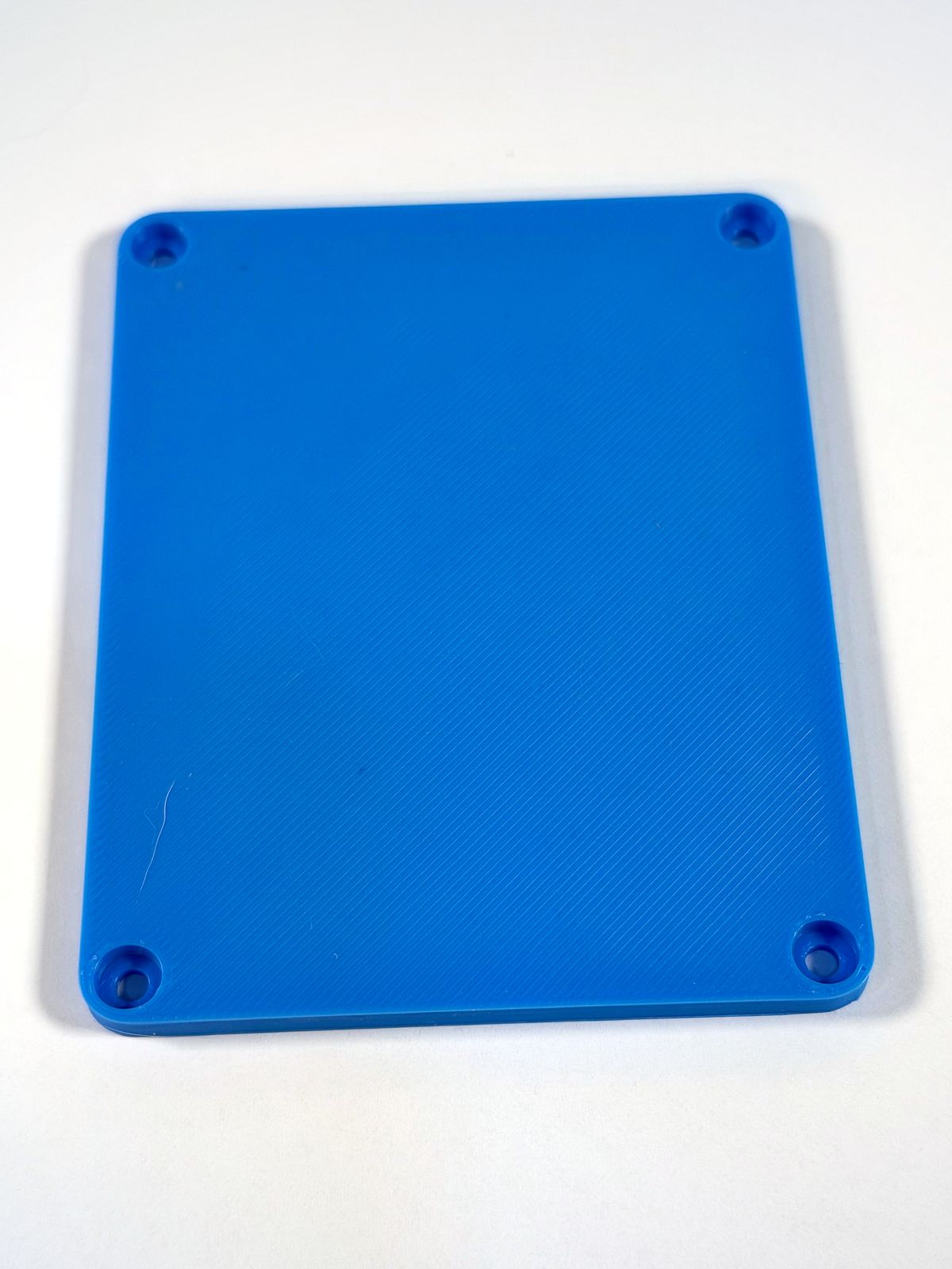
12Lid with counterbored screw holes -
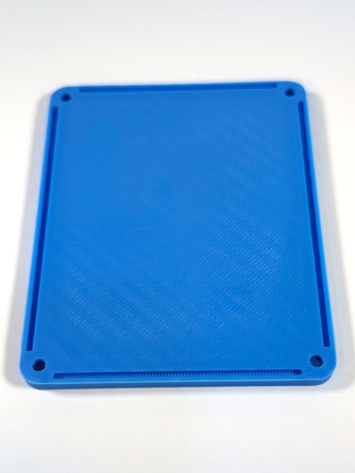
13Textured lid underside with a locating lip -
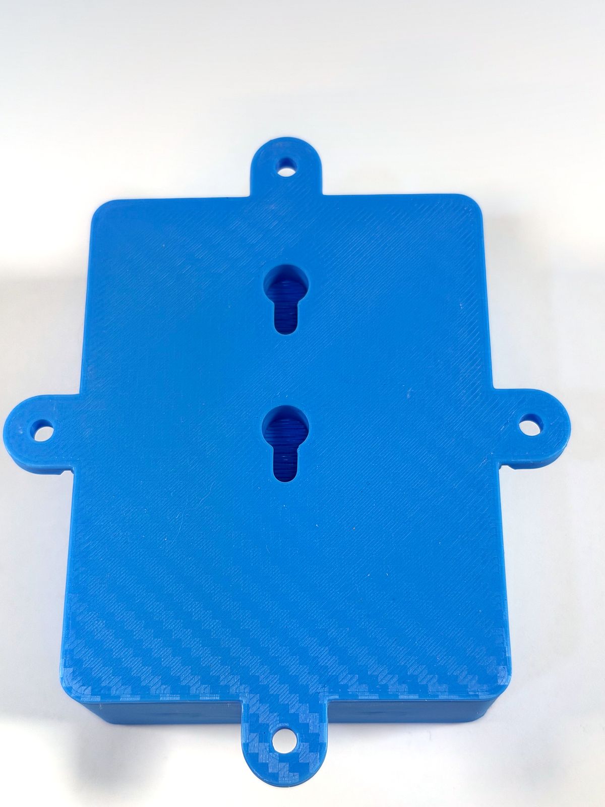
14Keyhole slots and four mounting tabs -
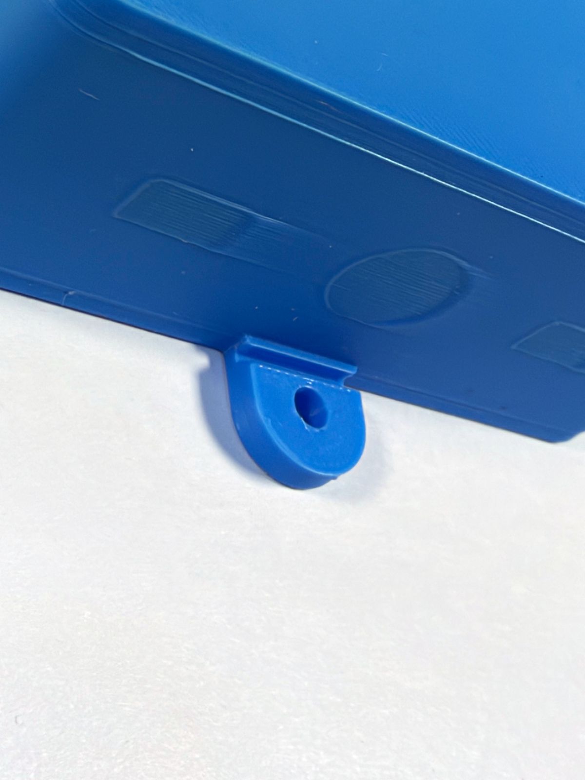
15Each tab has a score groove for flush mounting -
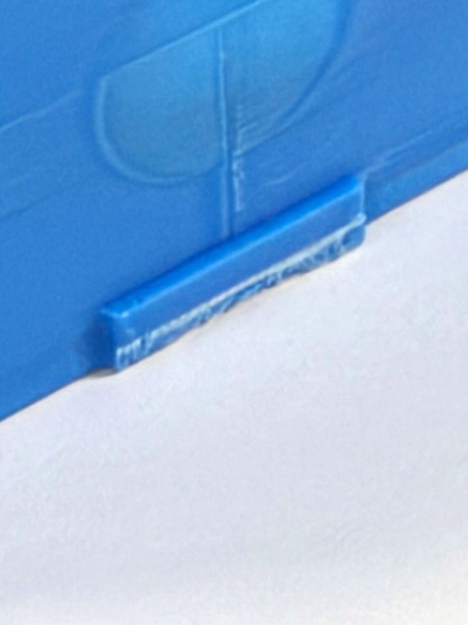
16Tab snapped off, from the 30-pin version (same tab design) -
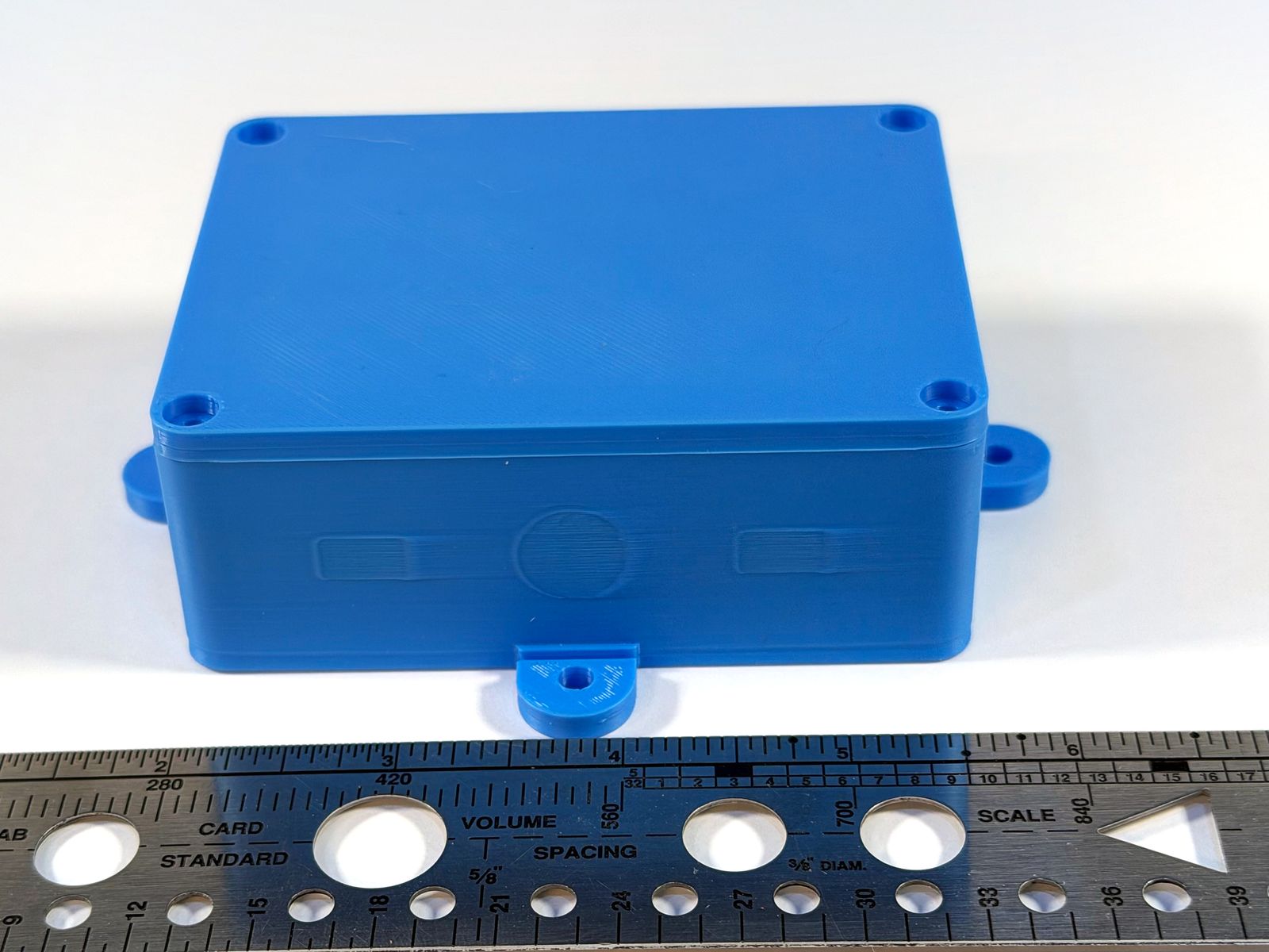
17Next to a ruler for scale (93.8 × 73.8 mm body)
After cutting
-
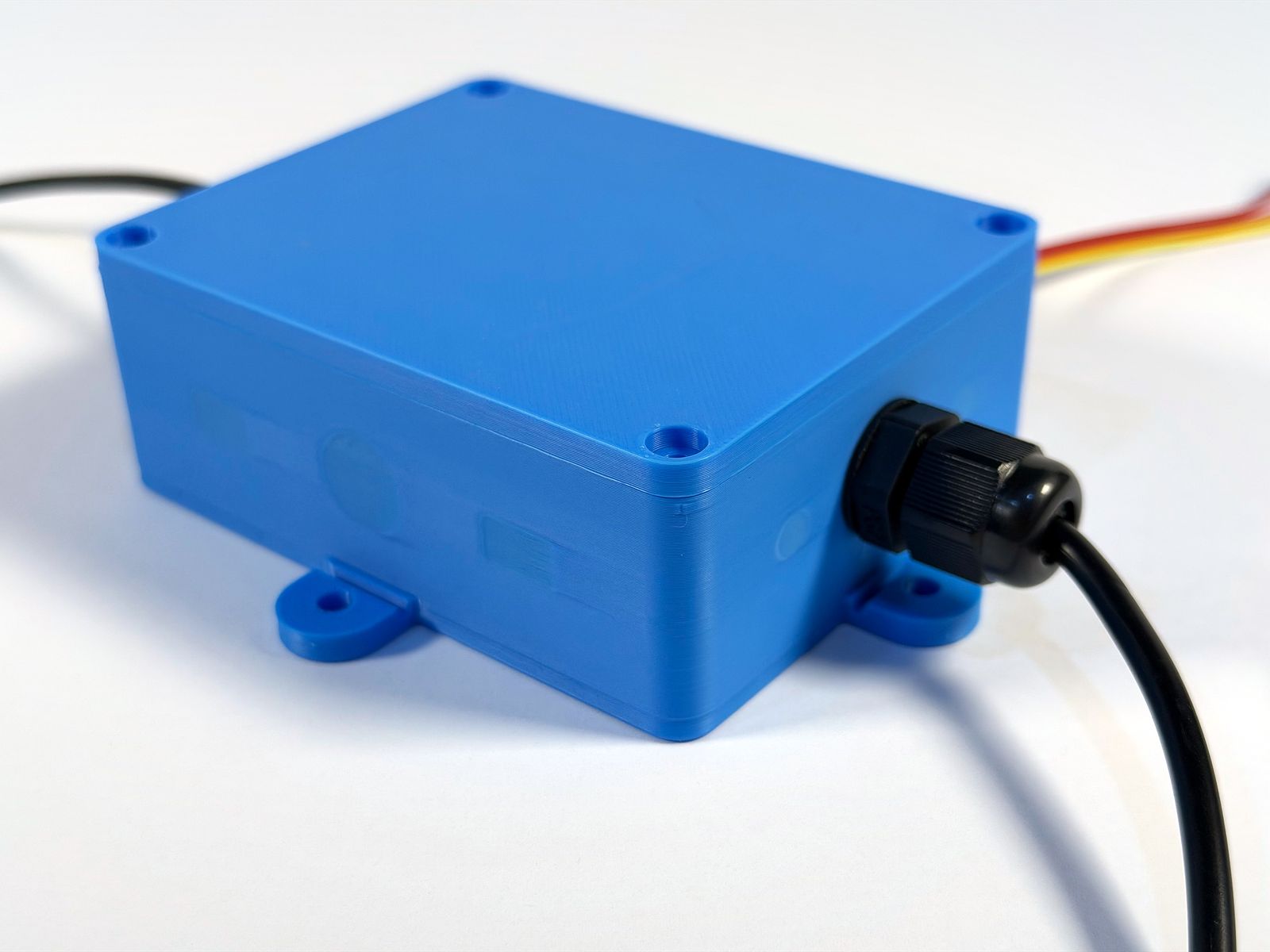
18PG7 cable gland fitted in the SWD end, lid on -
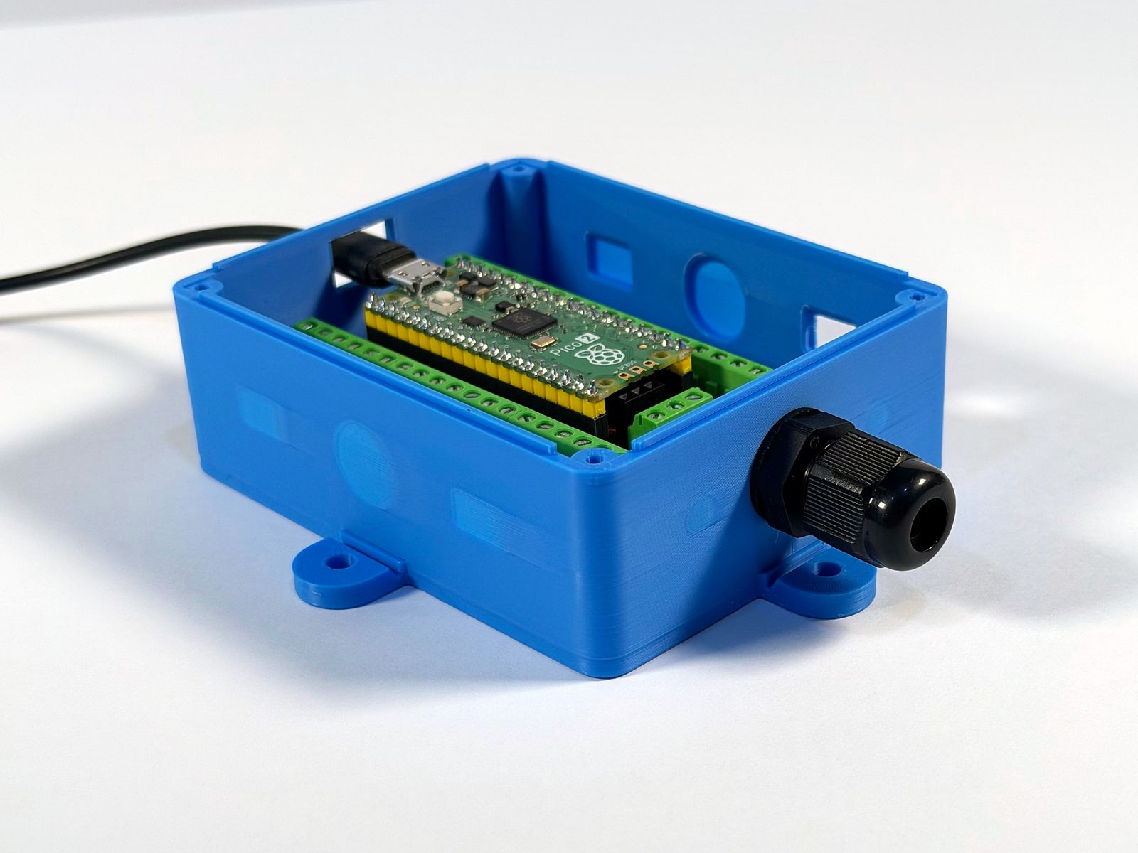
19PG7 gland in the SWD-end knockout -
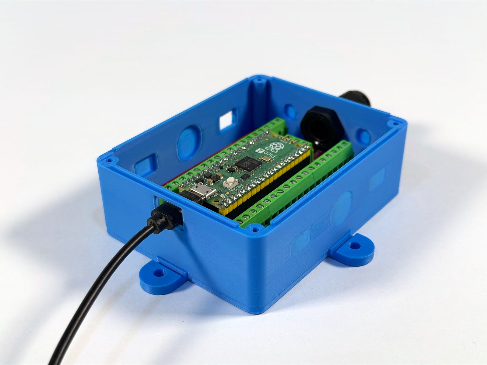
20The gland locknut sits between the wall and the breakout (about 2–3 mm to spare) -
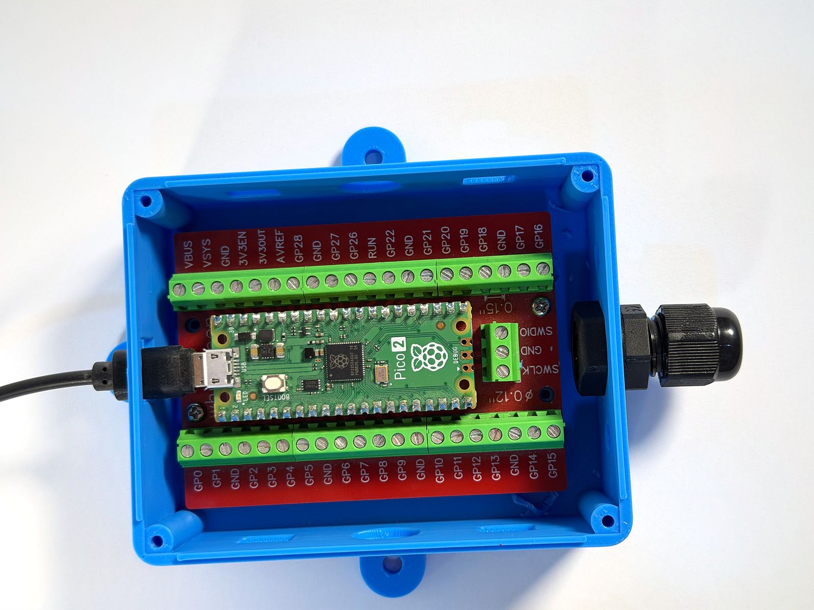
21Locknut in the gap at the SWD end -
22Cables through the gland and an opened slot, lid off -
23An opened slot knockout with a lead through it -
24Lid on: micro-USB, PG7 gland and a slot lead -
25Cables through the gland and a slot, lid on